Jarhyn
Wizard
- Joined
- Mar 29, 2010
- Messages
- 14,517
- Gender
- Androgyne; they/them
- Basic Beliefs
- Natural Philosophy, Game Theoretic Ethicist
So, I have a system I'm working on and having trouble finding any other instances of people approaching the problem
Essentially, I have a thermistor, a "thing that is being heated", and a heater.
The setup is that the thermistor, the "plant" is not the thing I am really principally interested in.
The issue is that when I hit it with a PID control loop, it controls very well to target the thermistor, but this causes a problem because the "thing that is being heated" is closer to and more responsive to changes in the duty cycle of the heater than the thermistor.
The result is that the thing I'm trying to heat up has a nontrivial moment in which it's temperature is more than DOUBLE the target temperature, as revealed by a linear response of the thing (it has a heat-dependent signal, but we cannot sample this that way while the system is running 'nornally', it can only be sampled this way in test)
As a result, we have a system that is going to be ignorant of when it is overheating.
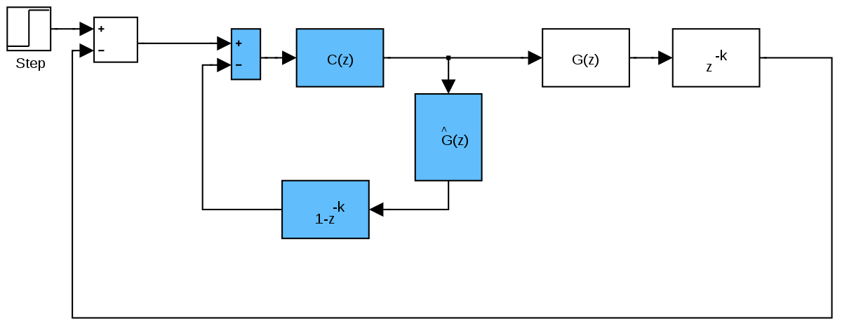
I know that I could probably resolve this with some sort of model, but what I have read on Smith Predictors does not seem to apply.
In normal operations I only have the one sensor, which can absolutely tell me when things are "stable", but which does not respond at the same rate as the target system, and cannot be used to feed back the throttle.
Is there something LIKE a Smith Predictor, for when the model has this kind of known error offset?
Essentially, the normal PID control looks like a well tuned loop that jumps and hits the temperature, but when measuring the target surface where the heat actually matters, there is an instantaneous spike in temperature right at the start of PID control to the new value in which duty cycle is obviously way too high.
Essentially, I have a thermistor, a "thing that is being heated", and a heater.
The setup is that the thermistor, the "plant" is not the thing I am really principally interested in.
The issue is that when I hit it with a PID control loop, it controls very well to target the thermistor, but this causes a problem because the "thing that is being heated" is closer to and more responsive to changes in the duty cycle of the heater than the thermistor.
The result is that the thing I'm trying to heat up has a nontrivial moment in which it's temperature is more than DOUBLE the target temperature, as revealed by a linear response of the thing (it has a heat-dependent signal, but we cannot sample this that way while the system is running 'nornally', it can only be sampled this way in test)
As a result, we have a system that is going to be ignorant of when it is overheating.
I know that I could probably resolve this with some sort of model, but what I have read on Smith Predictors does not seem to apply.
In normal operations I only have the one sensor, which can absolutely tell me when things are "stable", but which does not respond at the same rate as the target system, and cannot be used to feed back the throttle.
Is there something LIKE a Smith Predictor, for when the model has this kind of known error offset?
Essentially, the normal PID control looks like a well tuned loop that jumps and hits the temperature, but when measuring the target surface where the heat actually matters, there is an instantaneous spike in temperature right at the start of PID control to the new value in which duty cycle is obviously way too high.